
FDM vs MJF “Filament vs Powder Bed”
FDM (Fused Deposition Modeling)
FDM is a filament-based technology, it is also the most known 3D printer technology, starting costs from 300 € for a small desktop printer makes it a good entry-level technology with low-cost materials and low-cost maintenance.
Process explained: Wire-shaped plastic, so-called filament, is melted in a nozzle and selectively applied layer by layer. The most common materials are PLA, ABS, ASA and PETG.
Use:
- Low-cost parts
- Parts for the initial concept phase to check the proportions
- Very large parts (up to 13m)
MJF (Multi Jet Fusion)
MJF is a powder-based technology only used in industrial 3D printers, similar to the SLS technology (selective laser sintering), both are well known for their printing speed, good Quality-Price-Ratio and are commonly used for industrial grade applications.
Process explained: With a printhead two liquids are applied locally on a layer of plastic powder. They increase or suppress the heat absorption of the powder. Before the next layer of polymer powder is applied, a heat source melts the powder in the respective areas.
The most common material are nylon (PA12) and thermoplastic polyurethane (TPU).
Use
- Complex parts
- Prototypes with excellent mechanical properties
- Final use parts / Serial production parts
FDM vs MJF
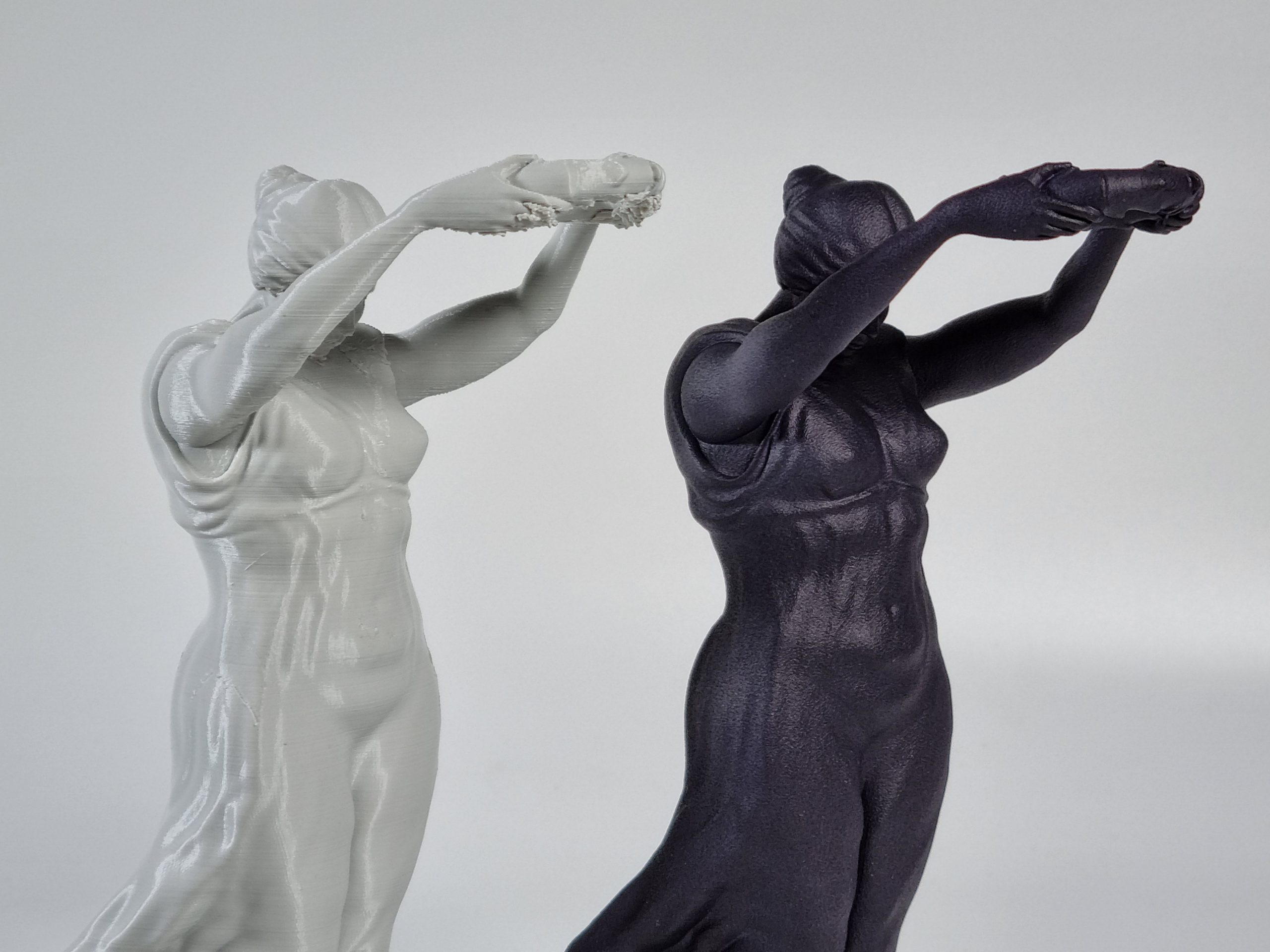
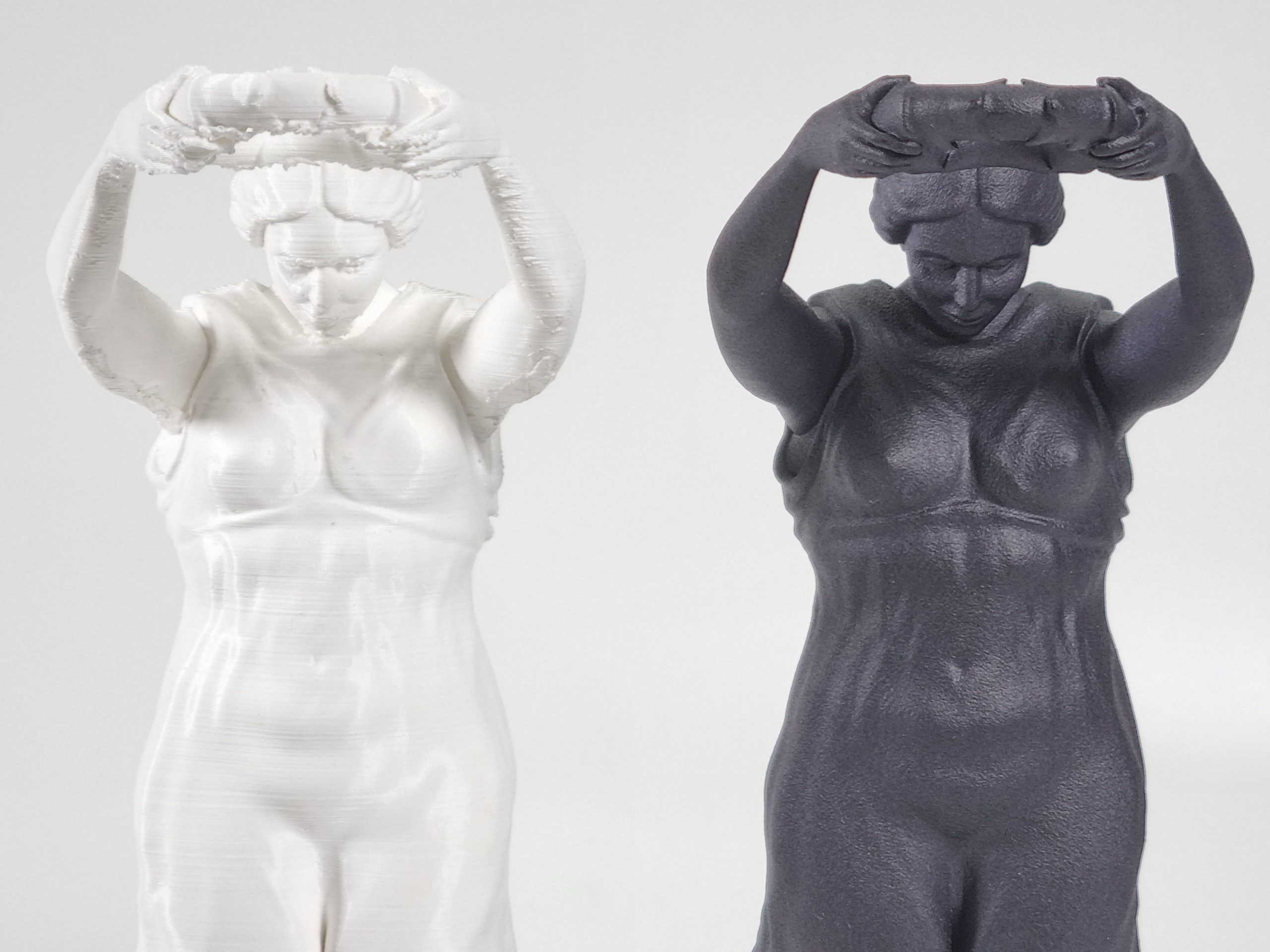
Surface quality:
Due to limitations on how FDM printers work, the individual layers will always be visible along the geometries of the printed parts.
MJF parts are printed with a layer height of 0,08 mm which results in a nearly smooth, slightly grainy surface, which is caused by the powder bed process. Compared to FDM, the individual layers are almost invisible.
Material properties:
FDM parts are not isotropic, which means when applying force to the printed parts, depending on the direction, the strength is not consistent, this it commonly known as “layer weakness”.
MJF parts are nearly isotropic, during the process the powder is being bond together, layer weakness is not an issue and forces can be applied independent of the direction, which is very important for complex shapes and industrial grade parts.
Tolerances:
Depending on the nozzle diameter, layer height and print orientation FDM prints have a general tolerance of ± 0,5 % (with a lower limit of ± 0.5 mm).
MJF prints in general a tolerance of ± 0,2 % (with a lower limit of ± 0.2 mm).
Design constrains:
Printing with FDM you have to consider design constraints such as wall thickness, overhangs and general complexity of your part. Overhangs are supported assisted by support material which has to be manually removed after printing.
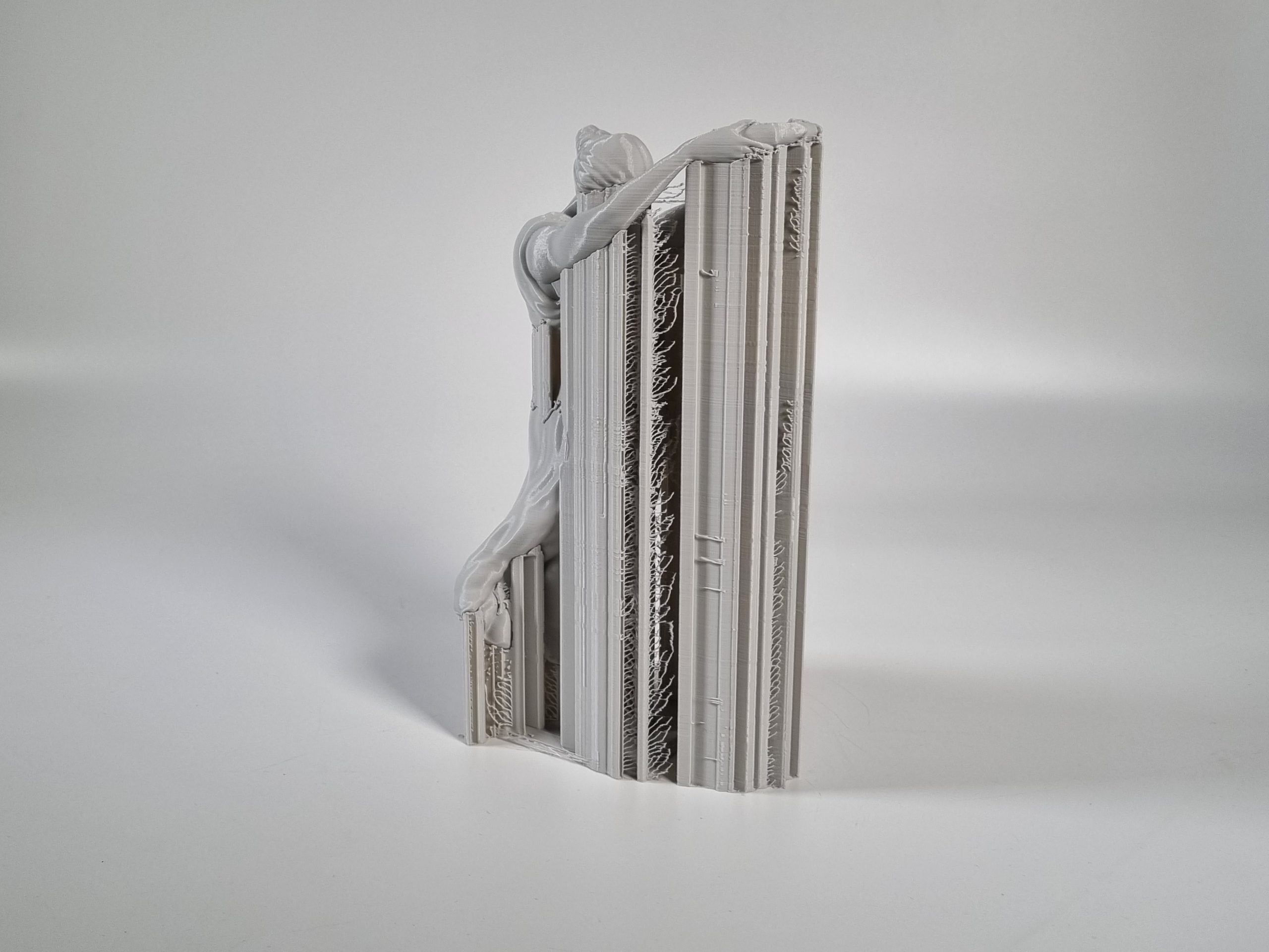
Due to the surrounding powder during the print, MJF parts don’t need any additional support material, which gives you flexibility in terms of designing your part. Moreover, interlocking parts can be printed in the same print job.
Build Volume and Print Time:
The build volume of FDM Printer depends on the dimensions of the build plate, parts can be stacked on the build plate in two directions.
The build volume of MJF Printers depends on the overall volume of the build unit, parts can be stacked in three directions. Due to the surrounding powder in the build unit, parts can be stacked on top of each other. In one print job, multiple parts are printed at the same time making it the ideal process for serial production.