3D Scanning – Which files can be exported?
What we did?
- 3D Scan
After 3D scanning an object, there are multiple possibilities of output files. Some are fully or semi-automatic, others require manual work.
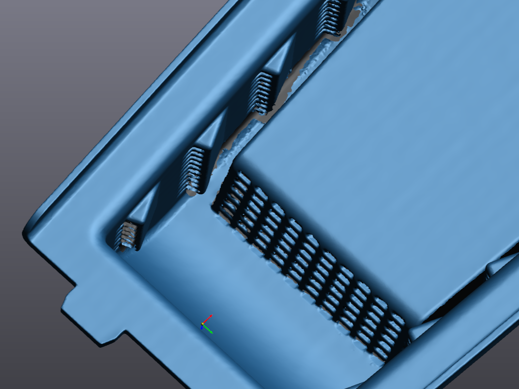
Unmodified STL
The standard output file from a 3D scan is a mesh file, usually in the .STL format. It may contain holes and noise from areas that are difficult or impossible to scan. They are used if you need to take simple measurements.
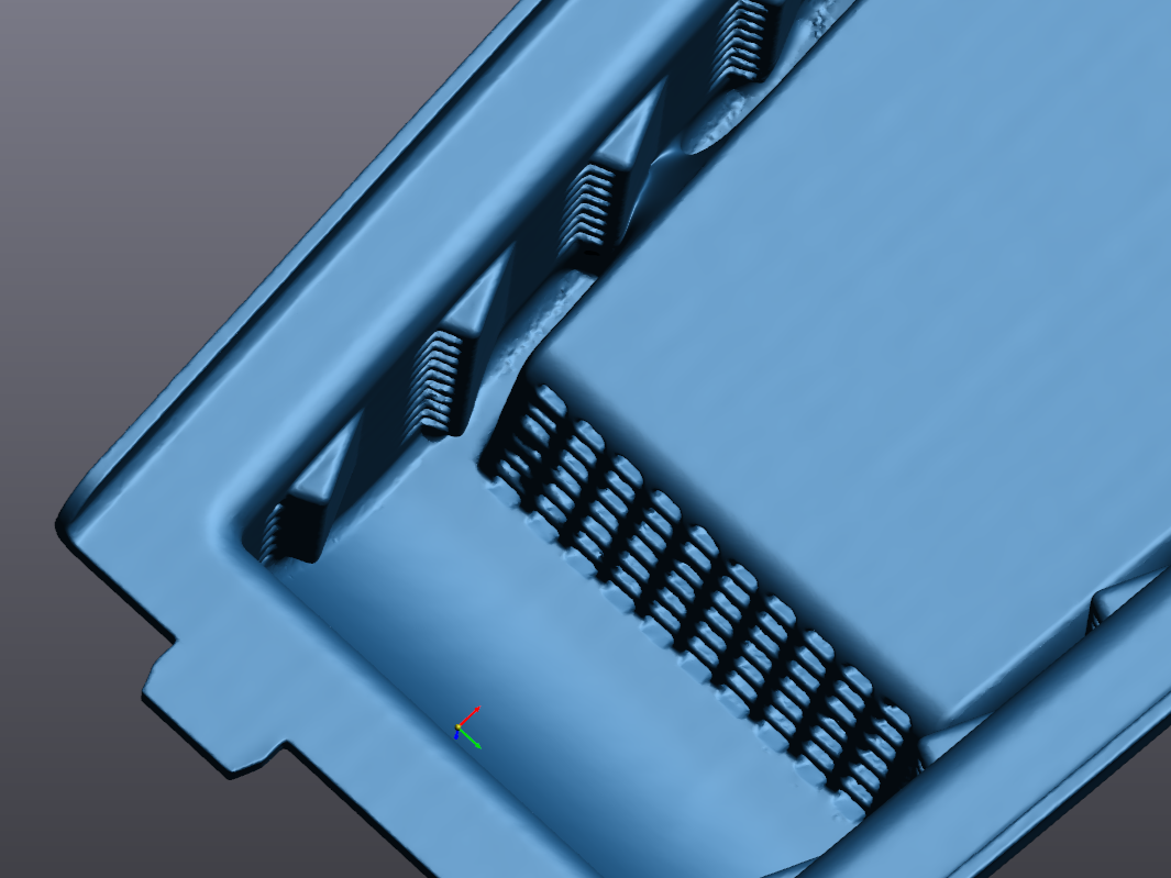
Watertight STL
A watertight mesh is needed if you want to 3D print your part. It is obtained by semi-automatically closing the holes in the digital part. While closing the holes might modify the part, as the software has to guess what the original shape was, that area can be adapted afterwards to remain functional.
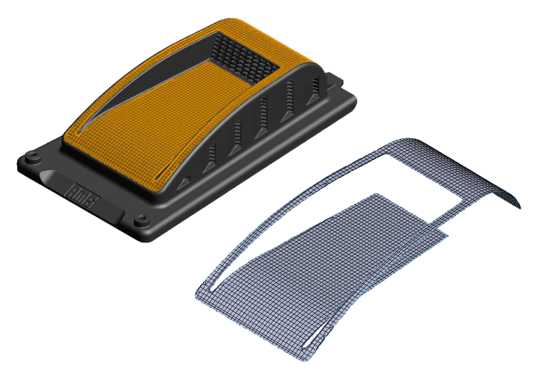
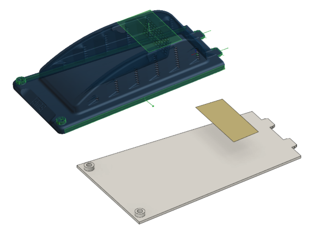
Surfaces STEP
We can manually place surfaces on a mesh, to create a CAD surface part file. These are provided in the .STEP format and are especially useful for objects with freeform surfaces. These surfaces cannot be used as is to create closed volumes.
Primitive Geometry STEP
If you just need the positioning of certain elements, for example holes and threads, we can manually create a CAD file containing their exact locations, represented as cylinders. The same goes for planes, spheres, and cones.
Partial reverse engineering
A partial reverse engineering is a manual process, where we design the part from the ground up with the precise measurements from our 3D scanner. We design only the areas of the part that you need for your application. This can take multiple hours depending on the complexity of the object. One major benefit from this process, is that we can adapt any dimension and add or remove features, to suit your needs.
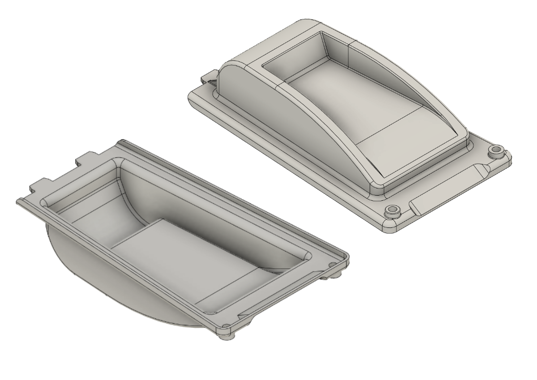
Complete reverse engineering
The complete reverse engineering of a part is the longest and most manual process. We design every small detail to obtain a 3D model that is identical to the physical object.